Some time ago, I recognized another home cockpit builder’s forum-thread. He’s building a Boeing 737-800 cockpit and he described how he constructed and installed a basic ventilation system. Thanks a lot, Daniel! 🙂 I was absolutetly excited by this idea! How literally cool would it be, to have a fully integrated ventilation system!
Not only because of the sound of the streaming air, which makes your cockpit experience more realistic – It’s absolutely no bad idea to care for some ventilation within your cockpit! You will have many devices generating heat, like Beamers, Monitors, Computers, Lighting and so on! Within a closed shell, especially in the summer your cockpit can turn quickly into a sauna.

Source: Smartcockpit.com
Enough reasons for me to get started with planning immediately!
After some research, I found a drawing of the original Airbus A320 ventilation system at Smartcockpit.com, which shows lots of air vents and a pretty large distribution system. I decided not to replicate it completely, but at least the two air vents above the Loudspeakers in the MIP and the air vents above the front windows, to obtain a good air circulation in the cockpit.
Furthermore, to me a very important goal of this subproject is to integrate the ventilation system into the Airbus system’s logic to reach a behavior like in the original A320. Meaning, the ventilation system needs bleed air to work. And bleed air is supplied either by the APU or by the main engines. So when the pilots want to start the engines, they are turning the Engine Mode Selector switch to Ignition/Start. Then the air condition in the plane is turning off, as the bleed air is now directed to the compressor, which turns the fan blades of the engines. You may notice this behavior as a passenger on an Airbus A320 if you pay attention to it.
Will it behave like an air condition?
Good question! To be honest, my first plans didn’t contain any thoughts about cooling down the air somehow, because the inside air will feel a little bit cooler through the Ventilation System for sure. But of course this can’t be compared to an air condition in any way. So some day I will have to find a solution to cool down the suction air. Maybe through an air conditioning unit or by an outside-inlet, whereby you have to be careful when humidity meets your electronic devices.
Enough with planning -> Here we go! The basic setup of the ventilation system was clear to me, so the next step was to find suitable parts.
The Blower

Bosch 12V Blower (0130007810) mounted on the MIP-Stand
Searching for a suitable blower, I finally chose a Bosch 12 Volts auxiliary blower, removed from an Opel Omega. You can find them cheap on ebay if you search for the number 0130007810. Here’s the Technical Specification in german as PDF. I checked out other options, like a PWM-controlled computer fan, too. But those didn’t seem to generate an air stream, strong enough to drive such a large distribution system like I needed.
The Bosch blower runs at 6500 rpm and it really has power – which is the next problem we need to handle. You wouldn’t want it to run on 6500 rpm permanently, as the noise and the air stream are too high. So this thing needs to be throttled! You can realize this by using high performance resistors in different strengths. More to this in the electronics-section down below. The blower is powered by a 12V/6A external power supply, that I also got from ebay. Because of its design, I mounted it with cable ties. As seen in the picture, the air is sucked in on the front and blown out upwards.
The Tubes
It took me several months to decide for the right kind of tube. My first thoughts were of using 30mm flexible tube, like it’s used for electrical house installations, because it is cheap to buy. Then I ordered 20 meters of 60mm flexible tube via ebay to use it as suction intake for the blower. But on testing it, the air stream generated a terrible noise, caused by the wave-profile on the inside. Beside that, the outlet air stream was also very weak. So it became clear, that the tube needs to have a flat surface on the inside. For a long time I tried to get some of those blue house ventilation tubes, but their diameter oftenly was to big and the tubes are sold pretty expensive, even from secondhand.
But then I finally found the right tube – on an aquarium equipment web shop. They were offering a very flexible tube with flat inside surface at several diameters in individual lengths. It wasn’t really a bargain, but the quality is very good! During my tests, the results were excellent: The tube provides a very silent and pretty strong air stream.
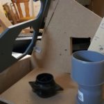
Swivel Eyeball Air Vents
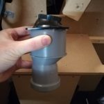
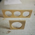
To realize the air outlets for Captain and First Officer, the challenge was to find suitable swivel air vents, fitting into my Loudspeaker-Panels. If found them on aircraftspruce.com for about 25 Euros per item. Delivery was quick and the quality is good. The vents can be swiveled in 40° to all directions and they can be compeltely shut, too. The only big problem was, to mount them into the panels. After several attempts, I finally fixed them with hot glue and very strong tape. Not really beautiful, but it works. Right next to the air vents there is a 75 to 50mm water pipe narrowing I got cheap from the DIY-market, to fit the diameter of the tube. Now it can be plugged in alltogether – but wait! Something is still missing!
-
- Air vent and waterpipe narrowing from 75->50mm
-
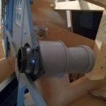
- The air vent fits perfectly onto the waterpipe and can still be fully swiveled
-

- Looking good! The right part of the vent will be covered later
-
- Just using hot-glue is insufficient and won’t last long
Air Distributor
The blower has only one air outlet, but I need to distribute the air to three separate places:
- Captain Side Loudspeaker Panel
- First Officer Side Loudspeaker Panel
- Top of the front windows
So what we now need is an air distributor!
As I couldn’t find suitable parts on the Internet, I decided to build it from wood. It should have one inlet and three outlets. Furthermore, it needs to consist about two inner pieces of wood that will split the airstream into three pathways, whereby the middle one will deliver the strongest air stream. The tube connected to the middle one will reach up to the cockpit front windows, while the other ones will each go to the Captain and F.O. side Loudspeaker-Panels.
I took the tube and cut a small piece off. The holes’ diameter is a little bit tighter than the tube, so I can screw it in with a little pressure and it fits tight. The grey water pipe is needed to equalize the blowers bent outlet. All of the parts were hot-glued together, as it sticks like hell and seals the whole construction against leaking air at the same time.
-
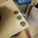
- The material is 5mm medium density board

-
- Sawing front and back end of the distributor

-

- Building a simple frame around the pieces

-
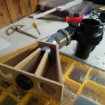
- Initial test and aligning the air stream directors

-
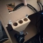
- Distributor finally mounted behind MIP-Stand

Installation and Starting Up
After mounting all the pieces and fitting the tubes, I ran a first test at full throttle 🙂 Take a look at the short video!
I’m looking forward to your comments and ideas! See you! 🙂


7 Comments
Vincent · June 13, 2018 at 4:44 pm
What a great idea! I just discovered your blog, it’s amazing! Thanks for your tips and good continuation in your passion 🙂
Marco · June 21, 2018 at 12:22 pm
Thank you very much for your post Vincent! I’m happy to read this 🙂 Best regards!
Pedro · September 24, 2018 at 11:57 am
Marco,
You just make my day! I found what I have been looking for the past month. can you share the reference number of the vents you got from aircraftspruce?
All the best
Pedro · September 24, 2018 at 3:09 pm
Hi Marco nice job. You make my day. could you share which reference number did you get fro the air vents.
Regards
Marco · October 8, 2018 at 8:01 am
Hi Pedro,
Thank you very much for your contribution. Of course I can share the Part Number:
05-04073 WHISPERFLO VENTILATORS Black
Best regards!
Marco
Mikko · July 25, 2023 at 1:28 pm
Hi! So what was the solution to control the blower from Overhead panel like in real plane? 🙂
Marco · August 1, 2024 at 10:40 am
Hi Mikko, my thought was to use several high capacity resistors with different strenght and to switch between them with a rotary switch. It’s not a beautiful solution, but the blower doesn’t work with PWM.