Hey Guys!
Some time ago I cabled my Autobrake-Panel with my Arcaze and Arduino modules. Here’s what I’ve done.
Starting point was the Autobrake-Panel I bought from JAA. It was delivered with Korrys, Switches and Buttons but did not consist about any backlight. So on the TODO-List there was the following:
- Interface the Autobrake-Panel with the Simulator -> described in this article
- Create a nice backlight -> described in a future post
Interfacing
To interface the Autobrake-Panel with the Simulator, I used my Arcaze-Modules, which are of good quality. I’m using an Arcaze USB-Module and an Arcaze LED-Driver 2. The Main Module shows up as a Gamepad/Controller in your Operating System and you can connect up to 40 Buttons or Switches to the Module. With the LED-Driver 2, which is connected to the main module, you can connect LEDs without using resistors, what makes the cabling much easier.
Warning: Arcaze Modules are currently only available from secondhand. The vendor doesn’t respond to any emails and there is no support anymore. If you should order a product on his website, it’s highly unlikely that you will ever receive your goods. This is based on my personal experience. If you’re setting up your homecockpit from scratch by now, I would recommend to use Arduino instead.
Let’s get to work!
Anyway, for my purposes Arcaze was sufficient and I bought the modules a long time ago, so it was obvious to use them by now. In a first step, I mounted both modules on a MDB-Board behind the MIP. Then I checked out the connections of the Korrys. It became clear, that each korry consists about six connection pins. Two of them for the switch/button and two for each LED, as the korrys consist about two separate chambers with different labeling and colors. So consequently, the cables from the button/switch are going to the Arcaze main module, while the cables from all LEDs are going to the Arcaze LED Driver 2 module.
-
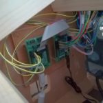
- Arcaze USB-Module and LED-Driver 2 mounted behind the MIP
-

- The Autobrake-Panel with cabling
-

- Labeling the connections
-

- Autobrake-Panel with labeled cabling
It is very important to label your connections. If there should occure a problem with a button or korry later, you will save a lot of time if you don’t need to search for the affected cables. In a second step, I sticked the six connections of every korry together with duct tape. So you can pull out all six connections at one time.
Creating an Input with the Arcaze Module
The next step was to configure everything in the Arcaze Software and to connect the cables. Here’s a step-by-step procedure how I configured the Autobrake-Panel-Functions in Arcaze.
- Connect your Arcaze-Module via USB to your Flight Simulation PC
- Launch the Arcaze Config Tool and you will see the main mask
- Create a new Configuration and set the emulation to “Digital Gamepad” and create a new Input for a button or switch of your panel
- Select the port where your button or switch is connected to, for example A01
-

- Arcaze Main Mask with configurations for multiple Functions

-

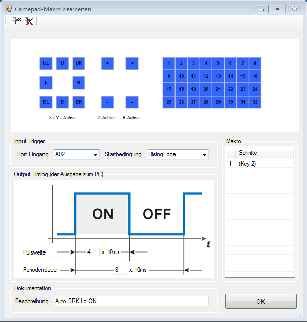
- Arcaze Settings for Pushbuttons
-

- Jeehell FMGS Configuration for Joystick-Pushbuttons

- If you’re configuring a button, you have to configure “Rising Edge” and “Falling Edge” – for each condition you’ll need a separate configuration. In my JAA panel, I know that the Autobrake Lo/Med/High Buttons are unfortunately real pushbuttons and not switches, like they actually should be – so I have to use Rising and Falling Edge here
- Please note that when configuring a pushbutton, you have to set the Periodendauer and Pulsweite like in my example. For switches it can both be 1
- If you’re configuring a switch, you have to configure “Repeat” – for example “Gear Up” and “Gear Down”, where I am using microswitches as described in my post regarding the Gear Lever here
- In the section called “Makro” you type in a number or a letter that will be sent to the Simulator when pressing your button/switch
After configuring this you have to write back the configuration to the Arcaze module. Use the according function in the main menu
- Now you can launch the Jeehell FMGS Config Tool and klick “Joystick Buttons”
- Here you just push your button or switch and it should be displayed as the number or letter you entered in the Arcaze config, “New Key N1”, for example
- Klick below the text “Button push action” and a list menu will open
- Then you can select an action that should be executed by Jeehell FMGS, for example “MIP ABK_LO” – to activate the Autobrake Lo Function
- You can also set a button release action. So if the button is pressed twice, the function is turned on and off again.
- Dont forget to klick “Finished” and then “Save Configuration”
- Your button should now work as required and Autobrake Lo should activate when the button is pressed – compare with the button in the visual Overhead-Panel and the message on the ECAM Status page.
Now you have created an Input and your Autobrake Panel’s button is working – but there is no LED in the Korry lighting up, for example when setting “Autobrake Lo”. Time to realize this, too!
Creating an Output with the Mobiflight Connector and Arcaze LED Driver 2
To control LEDs you need the following things:
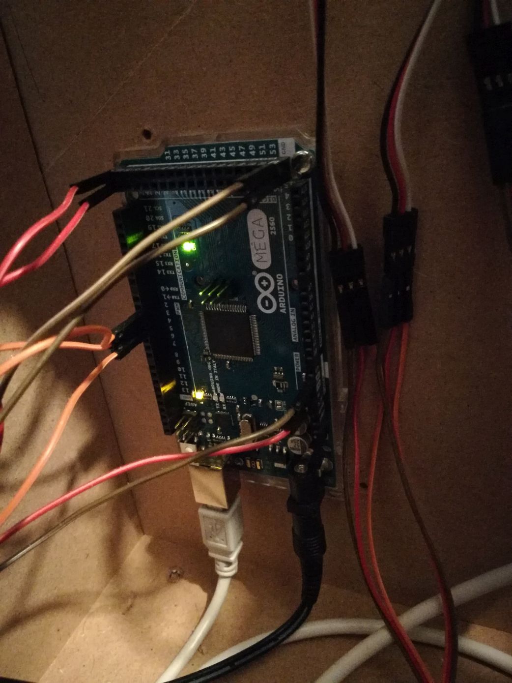
- An Arduino Mega 2560 Module, flashed with the Mobiflight Firmware (I recommend the 2560 as it is capable for the use of Servos, too)
- The Mobiflight Connector Software (available from www.mobiflight.com)
- The FSUIPC Software (free version is sufficient – available from http://www.schiratti.com/dowson.html)
The intention is, to flash your Arduino Board with the Mobiflight Firmware so you can control it with the Mobiflight Connector Software (from now shortened MF Connector). The MF Connector is a great piece of software that enables you to read offsets from your Simulation Software (Jeehell FMGS and FSX/P3D) and to trigger further actions depending on offset-values. For example to light up a LED or a display, trigger a servo-motor and so on. Those offsets are very important as they represent the current state of your aircraft’s systems. To make those FSUIPC-Offsets available, you first need to install the free tool “FSUIPC” by Pete Dowson.
Very important! If you are using Jeehell FMGS, please make sure that you have FSUIPC-Support installed on your FSX/P3D system. This is a feature you can select during the Jeehell FMGS-Setup. You will need it to read the Jeehell-Offsets with MF Connector.
I know this all seems to be a little bit complicated, but it ain’t. However I have to complete my personal setup: In my case, I have the LED Driver 2 module connected to the Arcaze main module. The LED Driver 2’s advantage is, that you don’t need any resistors in front of your LEDs. And: The MF Connector is able to control the Arcaze LED-Driver 2 module. (Hint: The LED Driver 2 needs a separate power supply to work).
Now here’s a step-by-step procedure how to configure your “Autobrake Lo” Korry:
- Check the FSUIPC Offset-Tables for the value you need: http://www.jeehell.org/Offsets.pdf
- The blue “Autobrake Lo” LED has the Offset 7393 and Bit Number 6
- According to this, create a new configuration line in the MF Connector like in the first picture down here. Name it “AutobrakeLoActive”, for example
- Then edit it and go to the FSUIPC-Tab. Some Offsets are already predefined under “Presets”. As “Autobrake Lo” is missing, you have to enter the Offset-Value and the Bit manually, as in pictures 2 and 3. To set the bit, klick on the square next to “Maskiere Wert mit” (Mask value with)
- Then change to the “Vergleichen” (Compare) Tab – here you tell the MF Connector when to light up the LED. Normally, if a LED is ligthed up, the Offset-status is 1. So in this case, the condition has to be: If value bigger than 0, set 1 (meaning turn LED on), if not, set 0 (meaning LED off) -> see picture 4.
- In picture 5 you configure your Arcaze Board in MF Connector and in picture 6 you tell the MF Connector to which Pin your Autobrake Lo LED is connected to. If you don’t use the Arcaze LED Driver, you can use your Arduino Board als LED-Output Board, too of course. But make sure that the board is delivering sufficient power to your LEDs, to prevent it from overload!
-

- 1) MF Connector main mask with multiple configurations
-

- 2) Offset-Settings in the MF Connector
-

- 3) Mask-Settings in the MF Connector
-

- 4) Comparing values in the MF Connector
-

- 5) Managing Arcaze Modules in the MF Connector
-

- 6) Setting the PIN to which the Autobrake Lo-LED is connected
If everything is connected and configured correctly then the blue Autobrake Lo LED should light up when:
- FSX/P3D is started
- FSUIPC is installed
- Jeehell FMGS is running and the aircraft’s systems are powered up
- Jeehell FMGS FSUIPC-Support is installed
- MF Connector is running
- Autobrake Lo Button is pressed
In the MF Connector main mask you can see the value that your offset currently has got. For debugging, you can switch on Autobrake Lo in Jeehell FMGS by clicking the corresponding button in the visual Overhead Panel. The offset value in MF Connector should change between 0 and 1.
The next step would be to do the same for the second LED of this Korry-> the green DECEL light, which comes up when Autobrake Lo is working/decelerating.
-
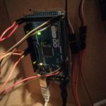
- Arduino Mega 2560 Board with Mobiflight Software
-

- Autobrake-Panel working

Please don’t hesitate to get in touch with me if you have any questions regarding this!
Best regards and have fun! Marco

1 Comment
Peter · November 20, 2021 at 5:15 pm
Hi,
how did you fix the panel into the MIP? How does it hold?
Best Regards
Peter