Hi Guys! Today it’s time to report about the progress my Pedestal recently made!
I started with reworking the Throttle. As you know, I’m using the common Saitek Pro Flight Throttle Quadrant with some modifications. If consists of Thrust Levers made from MDB which can be mounted on top of the original plastic levers.
The Throttle was yet mounted with the original Saitek holder. Not really beautiful to look at and much more important: The mounting position was far away from those in real A320s. So the goals of my modifications were set.
I started to design a construction that should look fairly like the original throttle. As you know, as real as it get’s – but affordable 🙂
Important aspects on this project are:
- Determine Original Throttle mounting height (My source is: Simpit)
- Determine Throttle inclination and lever/detent accuracy. The Throttle Quadrant has to be mounted with an inclination angle of about 45 degrees to reach the original mounting position
- Thickness of the trim wheels
- Stability of the whole construction, e.g. when moving the levers out of the detents or in case of cancelled Take-Offs
The Plan and Materials
As I had some suitable remains, I decided to use those 19mm MDB parts for the implied trim wheels and 20x20mm square timber as stops for the Throttle. The basic plate was made of 5mm MDB.

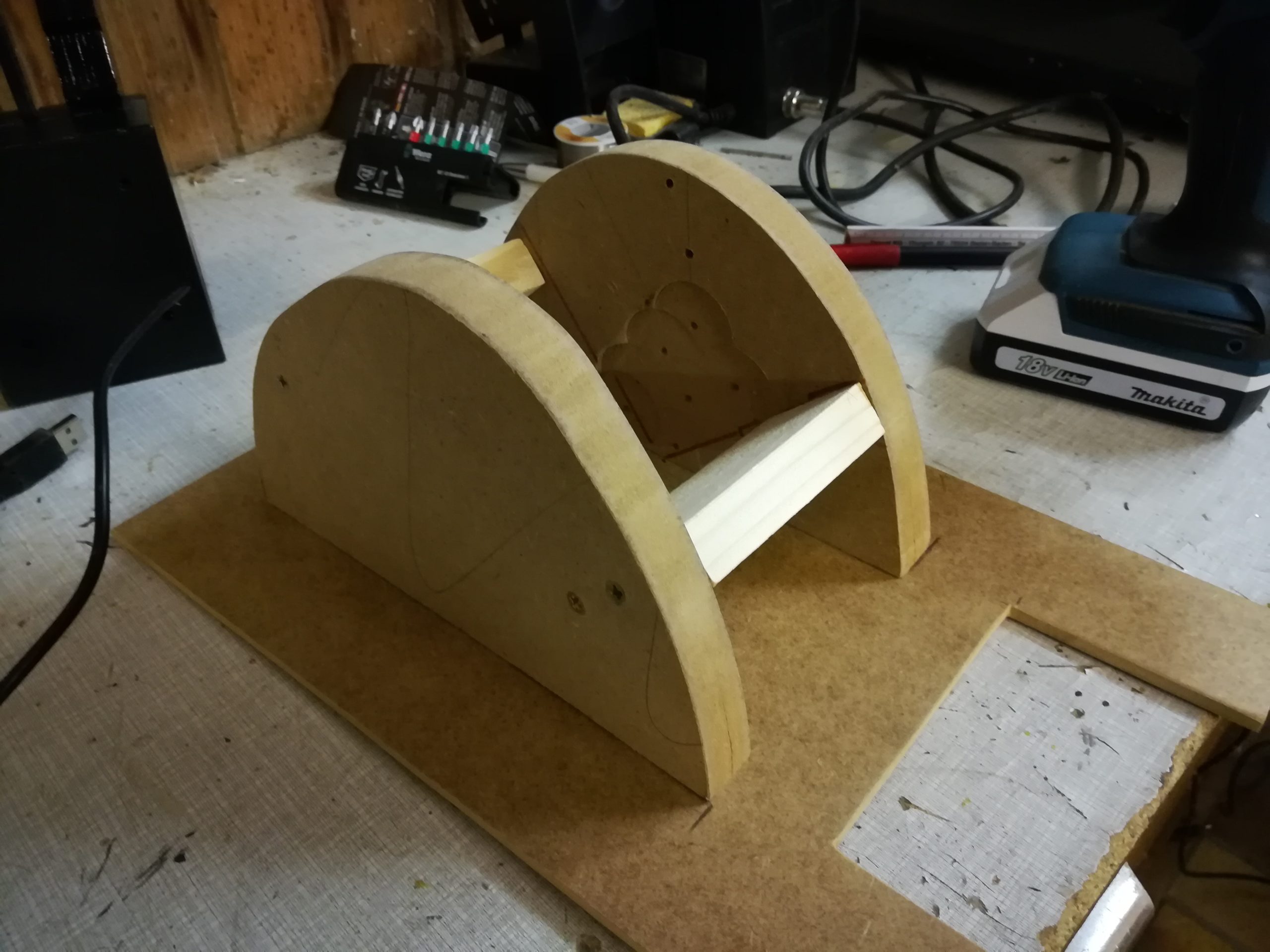

The trim wheels should fix the throttle very tight, so it wouldn’t be able to move in any direction. So high accuracy was needed when mounting the parts on the 5mm MDB basic plate. Please note: On the right hand side of the Saitek Throttle there is some kind of elevation that has to be considered before mounting. Finally the throttle is sitting extremely tight within the trim wheels and can now only be moved with lots of strength.
In addition, I used the original screw holes of the Throttle Quadrant to fix it in the correct angle. On the other side of the Throttle, there was no possibility to use screws. But it is sitting so tight, that screws were not needed.


And not to forget the hole for the USB-cable 🙂 In my case I also provided the notch for my Engine Start Panel. Looks pretty good for selfmade I would say 🙂


As a next step, I finalized the Pedestal carrier construction for the panels. The construction consists of two layers of 10mm MDB because of stability. Little bit tricky to saw the layers exactly to fit all parts satisfactory.
I don’t know, maybe I need to change this some day if mounting the panels becomes too problematic. For the moment, I will leave it with this, which means cutting the opening for each panel that has to find its place in my Pedestal. Btw: Mounting of the panels is done with simple M4 screws and nuts.


Pretty good result! With a little fine work and some paint in the right color surely nice 🙂
As additional information: The Engine Start Panel is from JAA Simulators and the ECAM Control Panel is from Skalarki Electronics. My Plan is:
The rest of the forward Pedestal will be equipped with Skalarki Components. The aft. Pedestal will be equipped with JAA Panels (DIY) I ordered years ago.


5 Comments
Antonio Sessa · June 15, 2020 at 10:11 am
Very interested, can you give me the radius of the circle used for the trim wheels?
I build some similar but yours is very beatiful!
Marco · June 25, 2020 at 2:28 pm
Hello Antonio, sorry for the delay! I’m going to measure them shortly and reply back! Best regards, Marco
Antonio · June 25, 2020 at 2:29 pm
Hi Marco, thanks a lot
Marco · June 25, 2020 at 2:41 pm
Hi Antonio, I just measured it. Unfortunately, it is not an accurate circle. The height at the highest point is 120mm. On the left and right bottom the radius is about 110mm. Hope this helps 🙂 Best regards, Marco
Antonio · June 25, 2020 at 2:41 pm
Yes thanks 😉