Hey Guys! Today I’m going to modify a common personal pc’s power supply to provide 5V and 12V voltage for my simulator! Why does that make sense? Let me show you why:
Did you ever count the number of power supplies you are using in your simulator? Nearly every component in your simulator needs power, no matter if just for backlighting or just to function correctly. Over time, the number of power supplies rises, and so does the effort for storing and cabling them. The more your simulator grows, the more you need to consolidate your systems and find ways to manage them easier.
ATX power supplies in general have many advantages. They are cheap to acquire and they are very powerful. Besides that, they are easy to handle, consist of a robust case and an active cooling. With some steps, you can transform a standard ATX or ATX2 power supply into a very powerful low voltage supply for your simulator.
I got me a used Xilence ATX2 power supply for small money. This one will later supply backlighting, the servos of my brake pressure gauge, panels like the ECAM Control Panel and surely much more.
I’m going to describe you my modifications as exactly as possible. Of course, you can also follow one of the countless tutorials on youtube for example.
WARNING! RISK OF ELECTRIC SHOCK!
Make sure your power supply has been disconnected from power 24 hours before you open the case, so all capacitors are discharged. Only open the case if you know what you are doing! You are operating at your own risk!
Here’s my Guide for the modification:
1. Open the case
Carefully open the case of your power supply and check, if any components like the fan or the power factor compensation (PFC) need to be disconnected from the circuit board to remove the cover completely. It’s not a bad idea to take some pictures, to ensure everything will be reassembled correctly after the work is done.

Open cover, fan-screws released 
The PFC sits above right 
Without the PFC, cover removed


2. Clean the inside
Now I recommend to clean the inside of your power supply – and especially the fan – from dust and dirt. I did this using compressed air carefully. In my case, the fan blades needed to be cleaned with a towel, too.
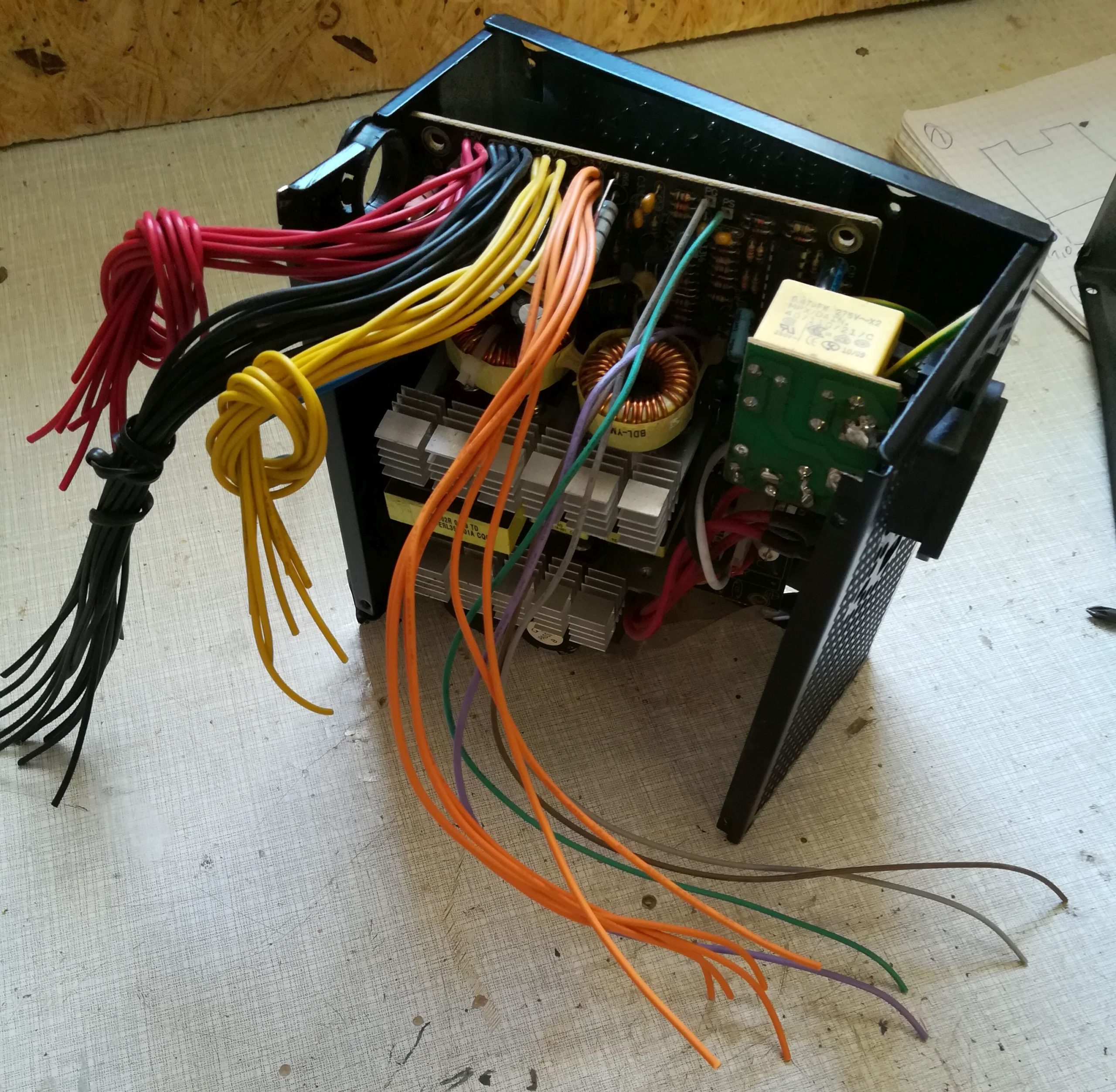
3. Group the cables by colour
Remove all cable ties, separate the cables of the harness and group them by colour. You can crop the 4pin and SATA plugs, but don’t crop the 20/24pin main connector now, you may still need it for the cable assignment later.
4. Modify the cabling according to your needs
Locate the cables of +3V (orange), +5V (red), +12V (yellow) and GND (black). Sort them by colour as in my picture below. Then check the diameter of the cables. Depending on the electric loads in your simulator, you will have to decide, if you need to “upgrade” the existing cabling. In my case, all of the cables installed were of 0,75mm². And there was many of them – for example there were 16 (!) cables only for GND!
I don’t want to handle so many cables of such a small diameter and I like to have reserves in cable capacity. So I decided to replace the existing cables by two 1,5mm² cables for each voltage I require. 1,5mm² cables carry up to 16A current each, so this should be enough for all simulator components. Consequently I unsoldered all cables at once, even if I knew that I might need to re-solder some of them later. To unsolder the cables, it was very helpful to apply some fresh soldering tin onto the solder joints, as this breaks the surface tension of the old solder. I recommend to unsolder at a temperature of around 350° Celsius.

The new 1,5mm² cabling 
Soldering-Action 🙂


5. Control wires and base load
ATX2 power supplies consist about so called control wires, which need to be powered before the power supply will start working. Check how many Pins your main connector has got. Here’s a link to the color scheme of the ATX/ATX2 connectors. In case of 24 like here, you will need to take care of the following cables:
The green cable represents the power on switch: If you connect it to GND, the power supply will always run when you connect it to 230V (like in my setup). Feel free to install a switch outside the case, if you want to control it manually.
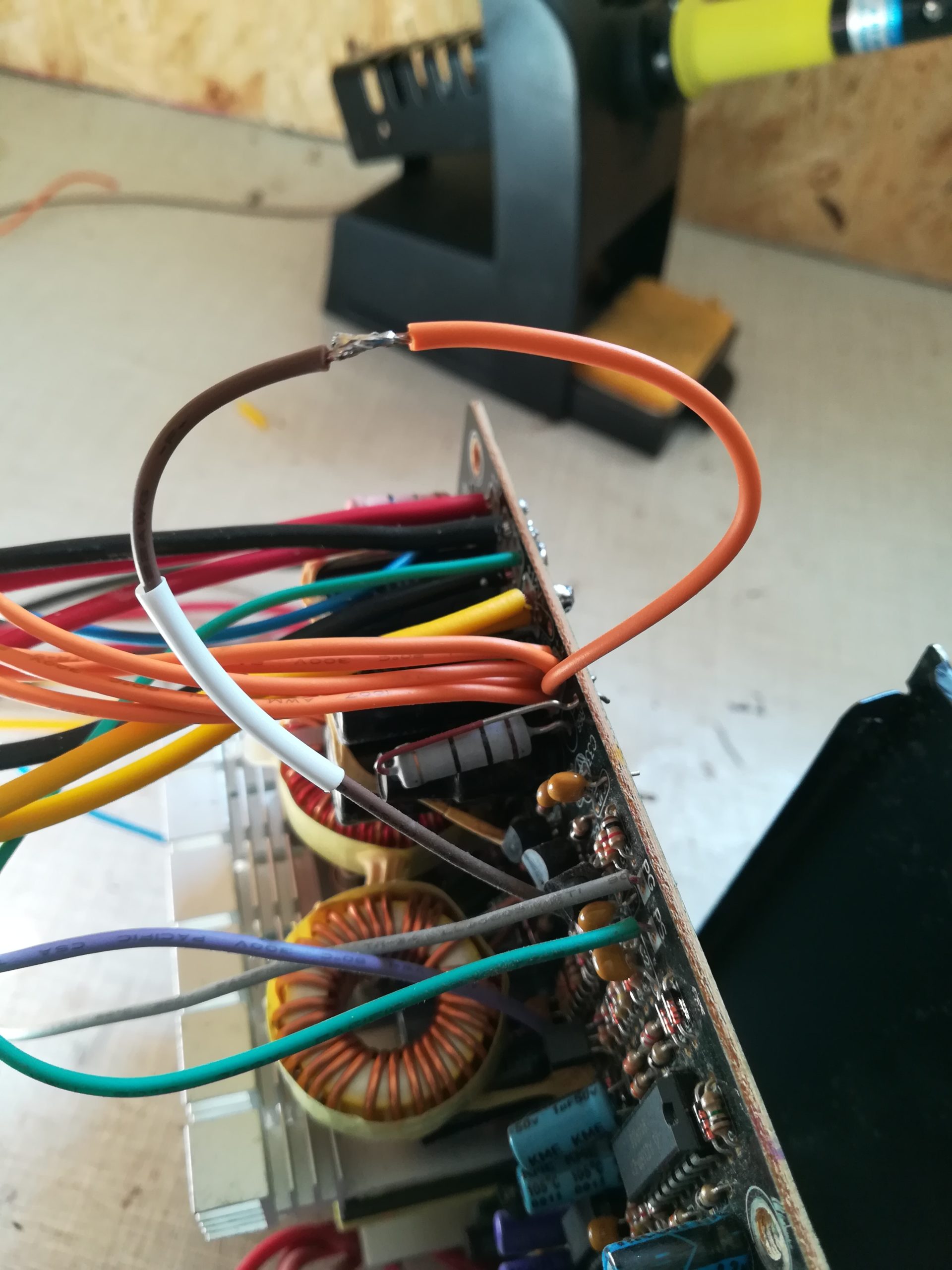
The 3.3V feedback cable (brown) needs to be connected to a +3.3V cable (orange). This is one control wire.
Power Supplies should not be driven without a so called base load. Otherwise it probably won’t work or you will have deviating voltages. To avoid this, you need to install a consumer within the 5V circuit. Some people use a strong light bulb. I prefer a high performance resistor with 25W up to 50W. Beware that those resistors can become very hot (up to 200° Celsius). Mount it in a way it can dissipate its heat to air and to the case. Put some heat sink paste on the bottom of the resistor, if available. Then connect it to +5V (red) and GND (black).
The remaining cables like the -12V (purple) or PG (Power-good) (grey) are not needed in my scenario and have been cut off and isolated with a shrink tube.

Look for shortages on the circuit board (PS = power switch, PG = power good) 
The +3V control circuit – brown and orange 
The high performance resistor is mounted in the airstream of the fan

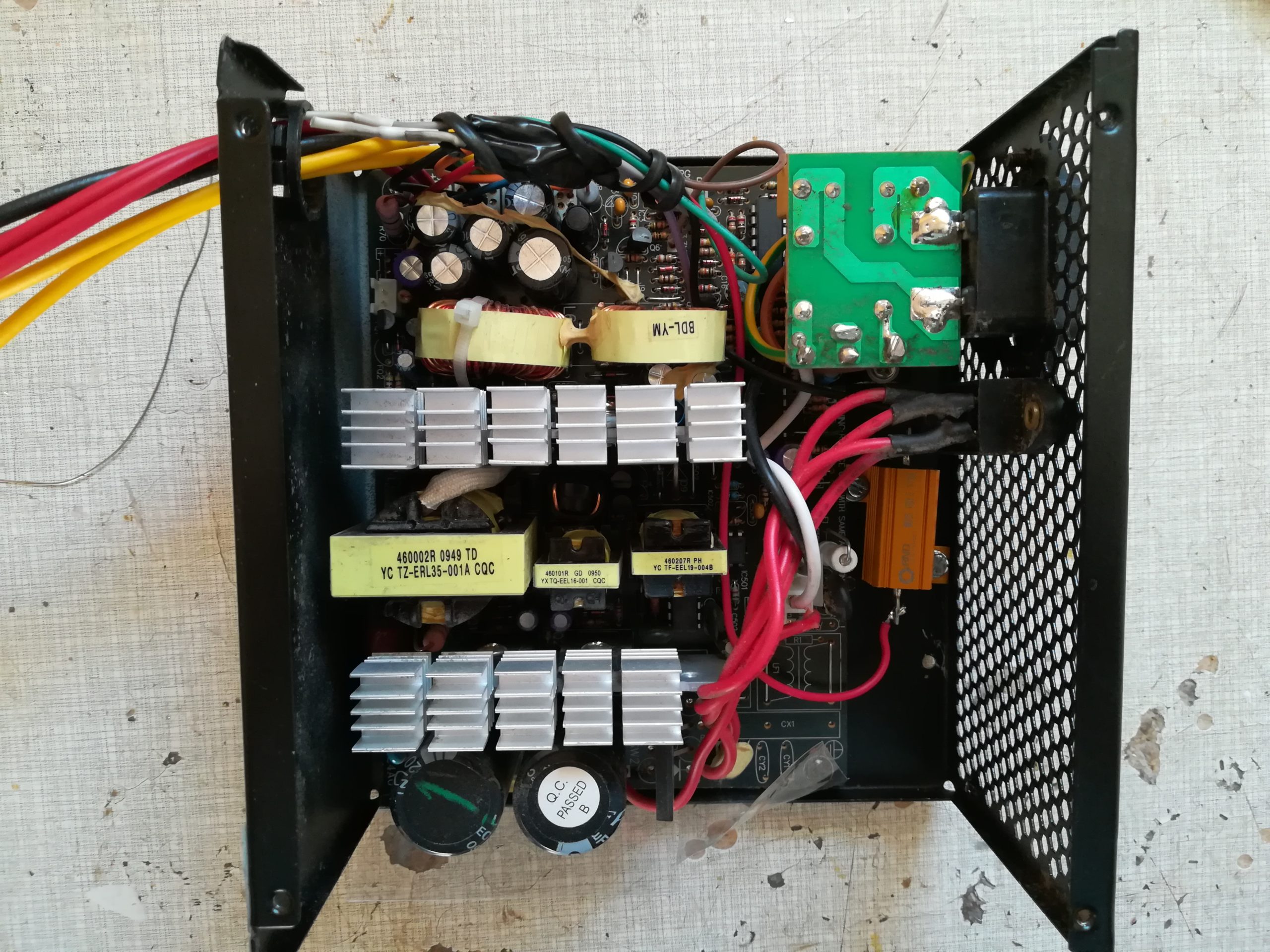
Now everything needs to be put together again! Hopefully you placed your resistor better than me, cause I needed to replace it as it was too close to the PFC at the first time. Take care that all cables are well stowed so nothing can block the fan. Also make sure to connect all components like the PFC and the fan.

The whole thing reworked 
Finished! 
5V is good… 
12V too 🙂


Before plugging the power cable in, make sure your 5V, 12V and GND cables are isolated from each other. I used screwless terminals (Wago type 221) for that. I recommend to measure the output voltage with a multimeter. If it works – Congratulations!! 🙂
6. Mounting in the Cockpit
The power supply finally found its place in the MIP-Stand of my cockpit. There was enough space, a good air circulation and in the end it was just a good place to distribute power to all components/all directions of the Simulator.
As mentioned above, I decided to use screwless terminals to provide 5V, 12V and GND. To mount the terminals properly, I made a clamp from a remaining aluminium profile which lays the cables and fixes the terminals nicely. The power supply and the cables still need to be fixed.

Measuring space 
Drilling some holes 
Could work 🙂 
Mounting beneath the MIP-Stand 
Labelling of the terminals will follow!


0 Comments