One point fewer on the todo-list of the MIP!
The first challenge was to equip my JAA Panels with suitable potentiometers and buttons. Fortunately I could get a pair of older A320-type Opencockpits-Panels via the flightx.net community. Thanks a lot to Florian at this point!
Equipping the Panels
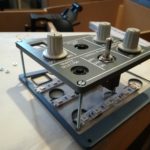
So I started to strip the OC-Panels and checked out what could be useful for my plans. The Panels consists of three layers of acrylic glass. Comparing the Opencockpits-Panels to the JAA-Panels, it was obvious to see that the JAA-Panels are smaller. So unfortunately the potis didn’t fit into the small holes of the JAA-Panels, and I had to use smaller ones I previously ordered from Hispapanels.com. Also the airbus style knobs don’t fit perfectly as they are a bit too wide – but knowing the price, if you need to buy a new one… I can live with it. Here are the first results:
-

- Mounting the first potis and buttons

-
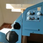
- PDF/ND Lighting-Panels equipped and mounted

The GPWS/GS (Ground Proximity Warning System/Glideslope) warning button is still in preparation, so I continued with the backlight!
Building the Backlight
Backlight was always a difficult topic to me, as I didn’t consist of good soldering skills. At least that was what I thought, until I was watching one of those fantastic soldering tutorials on youtube. With fresh motivation I started to make a list of parts needed. In my case, those were:
- Soldering station
- Solder
- Thin wires in different colours
- Amber coloured LED-Stripes
- Suitable carrier panel
- 12 Volts power supply
It makes a lot of sense to use a soldering station with adjustable temperature. The solder shouldn’t be too thin or to thick – 0,8 mm are perfect. To solder a wire onto the LED-Stripes, the contact points of the stripes should first be carefully prepared with abrasive paper. That makes the solder stick better. Then a ball of solder should be applied onto the contact poins. The very short end of the wire has to be coated with tin, too. Then, just put the wire onto the ball of solder and heat it up. It will merge perfectly.
-
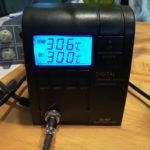
- Soldering station
-

- First LED-Stripe soldered
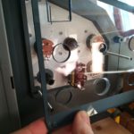
-

- The carrier panel with LED-Stripes
Fortunately, the Opencockpits-Panels are made of three layers of acrylic glass. One of them was perfectly convenient to carry the LED-Stripes. So I began to test, where the stripes need to be placed to get a evenly backlight. Then I drilled two more holes for the 50mm mounting screws and cut the LED-Stripes into suitable pieces. After sticking them onto the carrier panel I just had to connect the LED-Stripes with thin wires. The carrier panel was finally fixed with nuts.
-
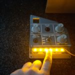
- Checking out the backlight intensity

-
- The carrier panel behind the JAA-Front-Panel

-
- The complete panel with backlight carrier panel

-
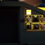
- Very nice backlight

-
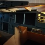
- View on the MIP

When more panels will be backlighted in the future, I need to wire them with a centralized power supply. I bought a used power supply of a PC for this. But before that I need to calculate the power demand of the LED-Stripes.
Next step will be to build the GPWS/GS warning button! Stay tuned 🙂

6 Comments
Franz Frei · October 23, 2019 at 2:48 pm
Hi Marco,
Many thanks for the inspiration to build the backlight! Could you please tell us what “Amber coloured LED-Stripes” did you use? There are very different colors names this way and I’m unsure which stripe to take.
Franz
Marco · October 24, 2019 at 9:20 pm
Dear Franz, thank you very much for your visit and your comment! Of course I can help you with your question. I’m using LED stripes from Hispapanels.com. You can find more details here: https://hispapanels.com/tienda/en/leds-displays-lcd/60-leds-flexible-strip.html
The picture doesn’t match with the real look. With some research, you should be able to find them on a webshop with cheaper shipping costs. Be aware that this LEDs are of type “high efficiency warm white” and so shining brighter than most other LEDs. Oh – and if it should be intersting for you: The power consumption of every LED-stripe (with three LEDs) is 50 mA. I just measured it for further cabling plans 🙂
Best regards and happy building!
Marco
Paulo Santos · March 30, 2022 at 8:12 pm
Just wondering how you did the panel with the text and graphics where the light shines through. All I can figure is they were printed out, cut out, pasted and blocked the paint when spray painting. Or was this done in some other way?
Marco · April 3, 2022 at 11:46 am
Hello Paulo, I didn’t make them. They were bought, originally from JAA Simulators (not to recommend!).
Muhta · July 19, 2022 at 5:53 pm
So, I was wondering how the light shines through the text and the buttons? Could you explain how that is done?
Marco · August 20, 2022 at 2:43 pm
The panels are made of several layers of acrylic glass. The top layer is paint-coated and with the text engraved.